Turbo Pumps
Turbomolecular pumps are in the same category as kinetic vacuum pumps. They are very similar to the turbine in terms...
Turbo Pumps
Turbomolecular pumps are in the same category as kinetic vacuum pumps. They are very similar to the turbine in terms of design. A multi-stage, turbine-like rotor comprising bladed disks rotates in a housing. "The blading" is the collective term for the blades of a compressor or a turbine. Invertedly between the rotor disks, you will find bladed stator disks with similar geometries.
Bearings
The use of two ball bearings to mount the shaft of a turbopump needs the arrangement of both bearings on the fore-vacuum side - this is because of the lubricants in the bearings. This leads to a unilateral (cantilever) support of the rotor with its huge mass.
Hybrid support provides benefits in this regard regarding rotor dynamics. Hybrid bearing assigns the application of two bearing concepts in a single pump. In such a situation, an oil-lubricated ball bearing is often attached to the shaft's end on the foreside. On the other hand, the high vacuum side is fitted with a wear-free and maintenance-free permanent magnetic bearing that usually centers the rotor radially. Typically, the oil used to lubricate the fore-vacuum side is kept in an operating fluid reservoir. There is a small dry safety bearing arranged in the magnetic bearing stator. A journal usually rotates freely in this bearing during normal operation. In the case of powerful radial shocks, then the safety bearing will stabilize the rotor and rotate only shortly. When the rotor is imbalanced, then the bearings on the shaft's both ends will produce much lower bearing-stressing vibration as opposed to the case of a floating bearing. On the high vacuum side, the magnetic bearing is often totally insensitive to vibration. What's more, this does away with the need for the bigger of the two bearings in a cantilever concept - with a size that limits rotational speed.
Alternatively, big pumps from a flange diameter of around 100 mm use bearings called 5-axis magnetic bearings. The rotor is usually levitated via digital electronic control through electromagnets and distance sensors. The degrees of freedom of a turbo rotor movement is monitored continuously and recalibrated in real-time. The lack of mechanical contact between the housing and the rotor keeps the vibration produced by the pump low. As for the rotor, it rotates around its axis of inertia. Any imbalance caused by erosion or one-sided coating (like in plasma etching) is often counteracted within broad limits.
Apart from the lack of oil on the backing-vacuum side, maintenance and freedom from wear are other advantages. In case of a power failure, the rotational energy of the pump results in the supply of electricity in the magnetic bearings. This allows power failures to be quickly bridged for a few minutes. In case the power failure takes a more extended period, the rotor will safely stop at a relatively low speed with the application of an integrated safety bearing. In the event of system malfunctions, the safety bearing will shut down the rotor to prevent any damage to the pump.
Drives/Motors
Brushless DC motors that can allow rotational frequencies of up to 1,500 Hz (90,000 rpm) are often used to drive the rotors. As a result, it will enable the blade velocities that are required for pumping the gases.
As of now, the drives are usually attached directly to the pumps. Typically, the power supply is 72, 48, or 24-volt direct current, produced by external power supply packs or built within the electronic unit of that pump.
Application - Producing Clean Vacuum
In general, turbopumps are ideal for producing a clean vacuum in the range between 10-3 and 10-10 hPa. Due to their high compression ratio, they conveniently keep oil from the oil-sealed pump's inlet area away from the recipient. For models with CF flanges and stainless steel housings, they could be baked out. As a result, these pumps are perfectly suitable for research and development whereby ultra-high vacuum needs to be achieved.
Turbopumps could be useful in evacuating relatively large vessels with the utilization of rotary vane pumps. When it comes to turbo drag pumps, the two-stage diaphragm pumps will be sufficient as backing pumps. Because of their low pumping speed, however, it will take a considerable amount of time to pump down these larger vessels. The diaphragm pump will also highly restrict the gas throughput of this pump combination. However, this combination is a very affordable solution for a dry pumping station. In most cases, it is used for differentially pumped mass spectrometers as well as other research and development or analytical applications. In case significantly higher pumping speeds are needed in the backing pump area, we advise using multi-storage Roots pumps from the process-capable backing pumps for chemical vacuum processes in the solar industry or semiconductor, or the ACP series.
Pumping stations consisting of a turbopump and a backing pump do need valves. Typically, both pumps are switched on simultaneously. As soon as the backing pump has attained the relevant fore-vacuum, the turbopump swiftly accelerates to its nominal speed and swiftly evacuates the vessel to a pressure of p < 10-4 hPa with its particular high pumping speed. The high rotational speed of the rotor can bridge short power failures. In the event of prolonged power failures, both the recipient and the pump can be vented automatically when the RPMs fall below minimum speed.
All the effects that have a role in evacuating vessels are outlined in Chapter 2. In that chapter, you will also find the description of dimensioning problems and the calculation of pump-down times.
Evacuating load lock chambers
Undoubtedly, evacuating load-lock chambers demands clean handling when moving the workpieces to be treated in a vacuum. In case these items are transferred from atmospheric pressure, the chamber must first be pre-evacuated through a bypass line. Then, the turbopump is connected between the chamber and the backing pump through valves.
Analytical applications
In most cases, mass spectrometers are applied in analyzers today. The injection and evaporation of fluids occur in the inlet chamber of the vacuum system. It takes several stages to reduce pressure, and orifices are used to isolate the individual chambers from one another. Since each chamber should be pumped, the goal is to combine the gas flows through taps on the turbopump via the skillful combination of turbopumps and backing pumps. When it comes to series applications, uniquely modified turbopumps with taps are often used. Apart from the SplitFlow 50 outlined in Chapter 4.9.3, client-specific solutions can be supplied.
What's more, helium leak detectors are equipped with turbopumps. In such a situation, the counter-flow principle is usually used; i.e., a mass spectrometer is found on the pump's high vacuum side. Because of the lower helium compression ratios of turbopumps as opposed to oxygen or nitrogen, the pumps serve as a selective filter for helium.
High gas loads-pumps in vacuum processes
In general, the turbopump provides two benefits when pumping high gas loads in vacuum processes. It produces a clean vacuum at the start of every process step, and may then pump down processed gas without any dangerous backflow. For the second step, the primary goal is to maintain a particular pressure at which the expected vacuum process should operate. In such a process, working pressure and gas throughputs will be identified by the application in question - which means a specified volume flow rate will be pumped at a specified gas throughput. Furthermore, when changing workpieces, it should be possible to obtain a clean intermediate vacuum promptly. Because these are contradicting requirements, a turbopump of the proper size for the needed gas throughput and the needed intermediate vacuum should be chosen. The process pressure will be controlled through an inlet valve (like a butterfly valve). A good example of how to dimension this type of pumping station is outlined in Chapter 2. The technical data specifies the maximum permissible gas loads, which should be taken to imply permissible continuous loads. Typically, this applies with respect to the assurance of proper cooling with regards to the specification and a backing pressure adjusted correctly.
Pumping abrasive and corrosive substances
If you're pumping corrosive gases, certain measures should be taken to prevent the rotor in particular and the motor/ bearing areas from corrosion. To properly do this, every surface that comes into contact with corrosive gas is either offered a coating or created from materials that can tolerate attacks by these gases. Designated inert gas flow is admitted into the bearing/ motor area in the fore-vacuum through a unique sealing gas valve. The gas then flows via labyrinth seals to the fore-vacuum area, combines with the corrosive gas, and is eventually pumped down by the backing pump along with the corrosive gas. When it comes to pumps with bell-shaped motors (for example, the ATH M series), there is a sealing gas on the Holweck stage's inner side that can serve as convection cooling and enhance the usable process window by lowering the temperature. Sealing gas is generally effective protection for the motor and bearing area, even for noncorrosive but dust-laden processes.
Should dust build-up, the turbo-blades could wear mechanically - this might necessitate the replacement and repairs of the rotor. Another point to remember is that deposits can be expected to develop in the pump, which will reduce service intervals. It is particularly necessary to make sure that deposits in the pump don't react to aggressive substances with moisture. Additionally, the pumps must be vented using dry inert gases and must be fitted with high vacuum flanges and sealed fore-vacuum when servicing is needed.
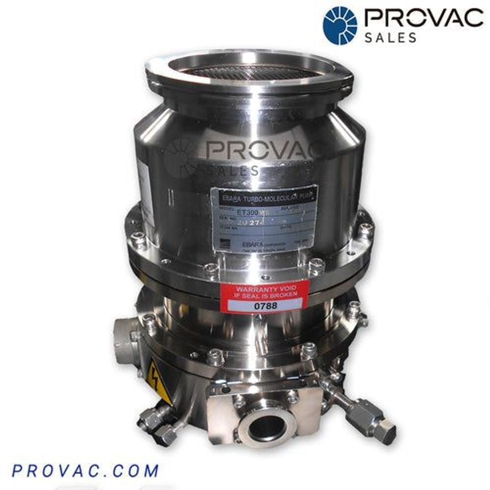
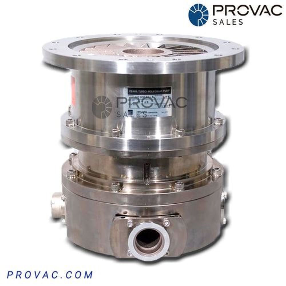
Ebara
Ebara ET-300WS Turbo Pump, Rebuilt
$ 7,246.00
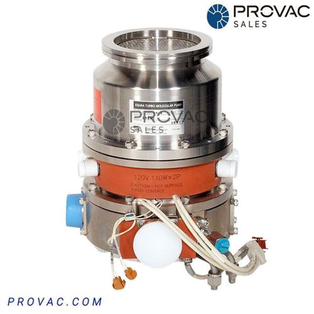
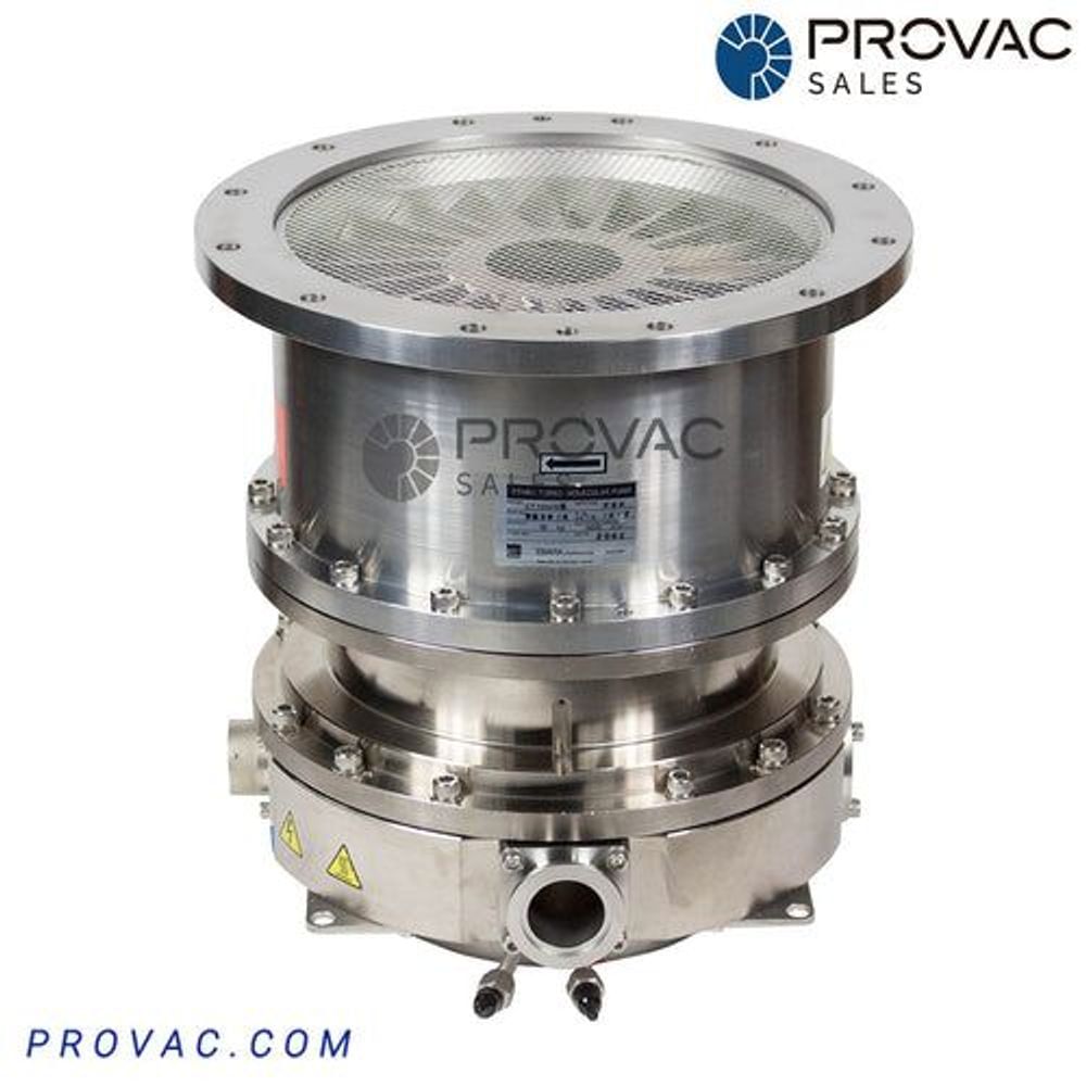
Ebara
Ebara ET-300WSA Turbo Pump
$ 7,030.00
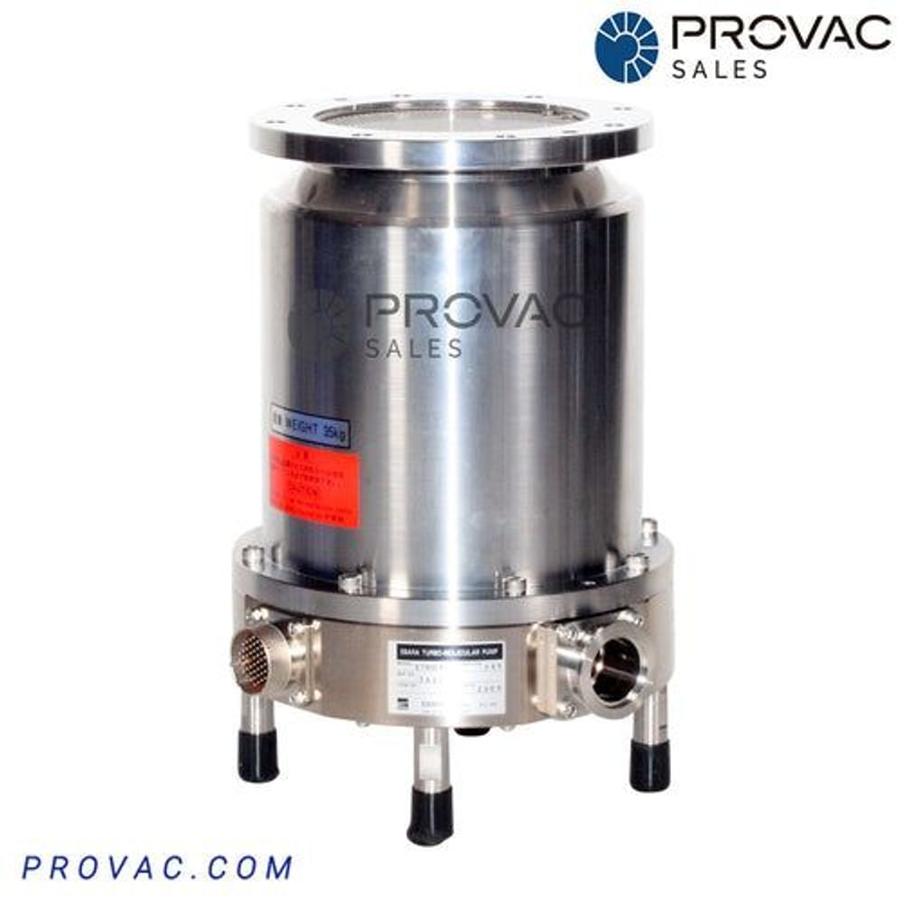
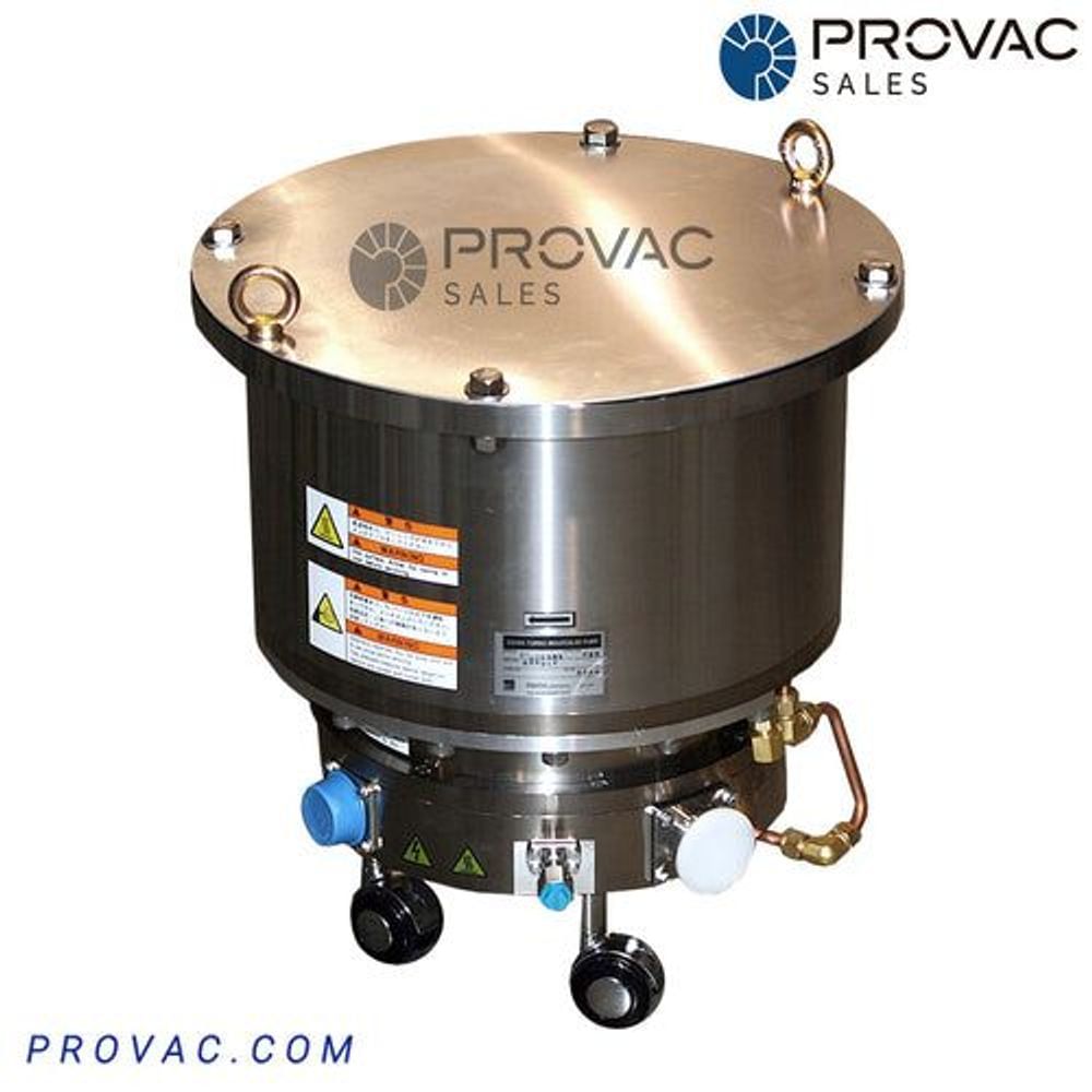
Ebara
Ebara ET-600WS Turbo Pump, Rebuilt
$ 12,113.00
Ebara
Ebara ET-800WS Turbo Pump, Rebuilt
$ 7,571.00
Ebara
Ebara ET-1600WS Turbo Pump, Rebuilt
$ 22,575.00
Ebara
Ebara ET-2500WS Turbo Pump, Rebuilt
$ 8,111.00